¶ Single phase
¶ Design mode
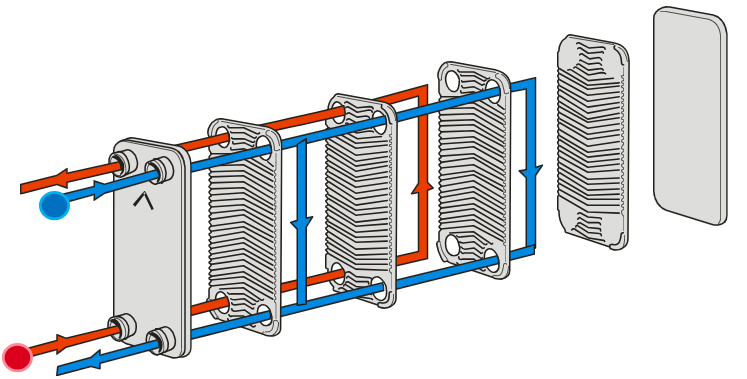
In the Design window it's possible to design a BPHE (brazed plate heat exchanger) based on specified conditions at which the heat exchanger is expected to operate. The designations Side 1 and 2 in the window relates to the red and blue flows in figure 1, which represents a one pass execution in counter current mode, the most common flow scheme in BPHEs. To design a BPHE follow the steps listed on the following page.
- Choose fluid for Side 1 (normally the hot fluid)
- Choose fluid for Side 2
- Choose Co - Current flow if necessary (Counter - Current default)
- Choose Exchangers (B - Types default)
- Specify the conditions necessary to make the single phase calculation:
- Heat Load to be transferred and/or
- Inlet temperatures on Side 1 and/or 2 and/or
- Outlet temperatures on Side 1 and/or 2 and/or
- Flow on side 1 and/or 2
- Specify the maximum allowed pressure drop on each side (50 kPa standard)
- Optional: Specify Number of passes (execution); Oversurface
- Choose Allow port switch (Adjusts Fluid to right Side based on the conditions)
- Choose AutoPerformance (yes or no, automatically calculate each unit in performance mode as well for the favoured unit)
- Press calculate
A list of suitable BPHEs are listed to the right of the SSP window. By clicking on one alternative, it's possible to view technical and dimensional data for the chosen design.
The best alternative from a price perspective is listed first. This is indicated by the PF (price factor) rating bar.
Red fields indicate lack/excess information
¶ Performance mode
In the performance window it's possible to determine how a certain heat exchanger (model/execution/plates) performs based on a specific key parameter depending on specified conditions.
Red fields indicate lack/excess information
¶ Rating mode
In the rating window it's possible to rate a certain heat exchanger (model/execution/plates) based on specified design conditions.
Red fields indicate lack/excess information
¶ Warnings
In the result window some warning or information text will appear. Click on the arrow next to the waning to get more information about what the warning means. Some common warning displayed in single phase calculation windows are:
¶ Port velocity on primary/secondary side is high (XXX)
Possible erosion in the connections and ports, due to high liquid flow. Try to decrease mass flow and/or select BPHE with larger ports. NB! SSP indicates the PORT velocity, never the connection velocities. If you are using titanium plates and connections, you can tolerate a slightly higher velocity up to 6.5 m/s.
¶ Min wall temperature on primary/secondary side is below the freezing point (XXX)
The minimum wall temperature is below the freezing point of the specific fluid. Design during these conditions is not recommende
¶ The calculation is exceeding the maximum NoP (XXX) for this BPHE
This warning shows in Performance and Rating modes if you are calculating with a larger number of plates than what in reality is possible to order.
¶ The calculation is exceeding the maximum number of passes (X) for this BPHE
This warning shows in Performance and Rating modes if you are calculating with a larger number of passes than what in reality is possible to order.
¶ Design at small LMTD
In single-phase applications, the LMTD (Logarithmic Mean Temperature Difference), for a certain design case, is defined as
In cases where LMTD is small, such as in many District Energy applications, the design temperatures have a very large impact on the heat transfer area (and thereby the number of plates) required to meet the case. A small change in e.g. outlet temperature on one side can correspond to a substatial change in required heat transfer area, and thereby price.
¶ Heat transfer area and LMTD
The capacity or heat load (energy flow from warm to cold medium) can be defined as
If LMTD is very small, the heat transfer area must be very large in order to meet the case. Then a small change in LMTD generates a large change in required heat transfer area.
For example, if LMTD = 1 K and A = 400 m2 and LMTD is decreased by 0.1 K, which is a decrease of 10%, then A must be increased by 10%, which means that the required heat transfer area is increased by 40 m2.
¶ Selecting BPHEs for small LMTD cases
When selecting heat exchangers for cases with small LMTD (< 3 K), it is important that you think about this relationship. For such cases, you should do a case-specific sensitivity analysis where you investigate how a small change in LMTD affects the required number of plates.
¶ If used for residential of commercial buildings for heat load lower than 16000000 Btu/h (4689 kW) and flow rates lower than 1200 US (4542 l/min) a AHRI certified model can be offered. Please contact your local SWEP sales office.
SWEP AHRI Certified Products can be offered to you for water/water applications that directly or indirectly serve either of the heating, cooling or tap water system in any kind of building. The AHRI Certification (Air Conditioning, Heating and Refrigeration Institute – www.ahridirectory.org ) is the only globally accepted third party program that randomly tests the performance of a product and verifies it against the selection software. An AHRI Certified product from SWEP can be offered for flow rates up to 1200 gpm (4542 l/min) and/or a heat load up to 16,000,000 Btu/h (4689 kW). SWEP AHRI Certified products has gone through a strict testing procedure and hence has a different denomination starting with AB e.g. AB10T to distinguish them from non AHRI Certified Products. The AHRI certified products can be calculated in a separate window that is only available for SWEP employees so please contact your local sales representative for more information and help in selection.
¶ AHRI certificate is valid due to parallel units
When a too high flow or capacity is added as input in the AHRI window the flow and capacity are divided into more than one unit to provide a result. This to be able to stay within the AHRI certificate which are valid for flow rates up to 1200 gpm (4542 l/min) or a heat load of up to 16,000,000 BTU/H (4689 kW). If specification is outside these values the AHRI window will not provide a result.
¶ Maximum number of plates is XX given connections on both sides
The limits in the information text is based on 54 mm connections on both F&P sides. Having connections only on one side allows 20 additional plates.
Customizing
The customizing system is set-up to allow above plate numbers for the Landskrona plant only. A CN-request will allow placement of higher NoP’s based on the plant and connection placement. This means to request configurations with the new plate limits the system will require selection of Landskrona as Production entity:
¶ SP/2P Units
A SP/2P unit is two units that will be connected in serial, with the same number of plates in the different units. The 2P execution is done by the help of connections between the units. The units will be ordered as two 1P units.
¶ Please note the importance of using the right oil properties (affects the HTA).
Oil properties may differ between oils, also within same supplier. Viscosity grade, VG, is regulated by ASTM D445 but heat capacity, Cp, is not.
Example: Shell Tellus hydraulic oils are available in more than 10 variants within ISO VG 46, e.g. “S2 VX46” or “M46”, but Cp differs more than 10%. If the BPHE is pressure drop limited on oil side, higher Cp will reduce mass flow, m ̇, to achieve same heat load, Q.
Q=m*Cp*ΔT
Less mass flow → less pressure drop → reduction of plates Standard hydraulic oil cooling case (60-50°C/20-28°C) and Q=50kW reduces HTA by 15%.
B10Tx50 → B10Tx44