¶ Connection impact
It simplify calculating the connection pressure drop and velocity to help guide the user to the correct connection selection.
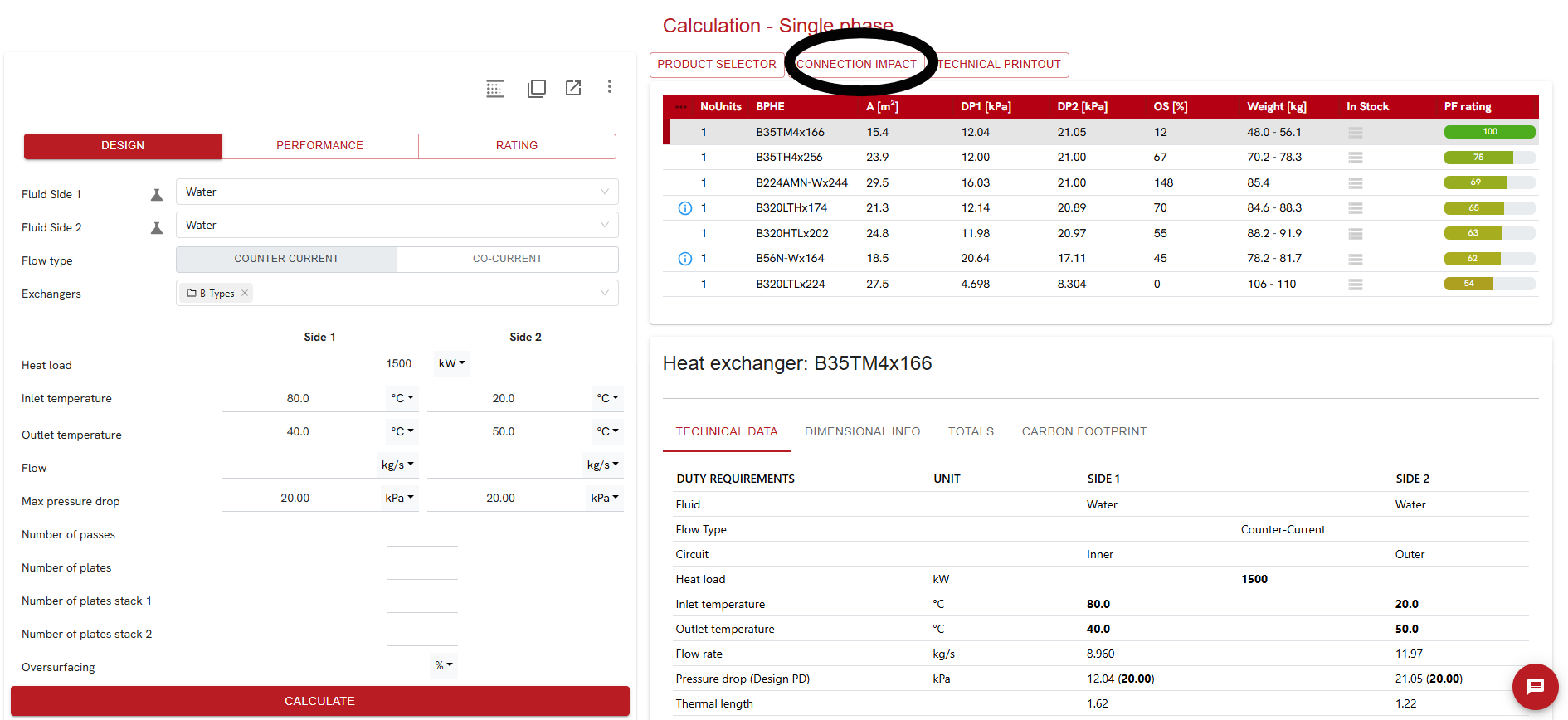
¶ Accessing connection impact tool and selecting connections
Once a user have calculated and selected a BPHE it is possible to click the connection impact icon in the tool bar.
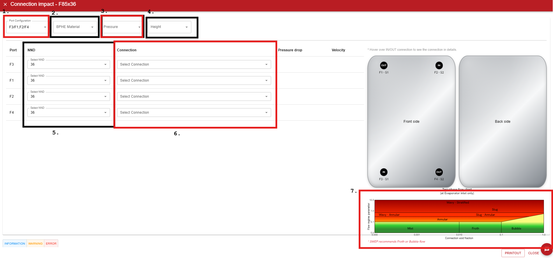
¶ Functionality
Connection impact tool consist of following parts:
- Port configuration selection
- Material filter
- Pressure filter
- Connection height filter
- Available Nozzle neck diameter (NND) for each port
- Available connections for each port
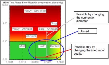
- For evaporators a flow regime chart is displayed
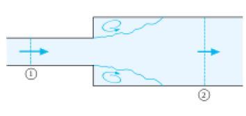
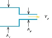
¶ Pressure drop calculation
Pressure drop in the connection is calculated as a sudden expansion/contraction pressure drop calculation.
¶ Printout feature
When clicking printout button, the user will obtain a document with all the BPHE data for the calculation case, same function as print button in SWEP SSPTM main interface. The difference is that the "pressure drop– total" now include the connection pressure drop.
¶ Recommendations
¶ Velocity limits for single phase fluids
Connection velocity is limited due to pressure drop issues. When the pressure drop increases, the pump power increases for a given water flow.
The velocity limit in the connection is different from the velocity limit in the plates and ports. This velocity limit is considered in normal SWEP SSPTM calculations, where warnings are given on excessive velocity in ports and/or channels, which may cause erosion in the BPHE.
For liquids, velocity limit in ports and plates is set to 5,5 m/s
For gases, velocity limit in ports and plates is set to 100 m/s
For steam applications velocity in ports and plates is set as per graph in Fig .6.

¶ Velocity limits for condensers
Condenser inlet velocity should be 5–25 m/sec to ensure good distribution and condenser performance. For condenser outlet the recommendation is 0.5–2 m/sec to ensure good condensate control.
¶ Velocity limits for evaporators
The size of the inlet connection should correspond to a velocity between 10 and 25 m/s in order to ensure a good distribution of the fluid, see "flow patterns" below.
Connection outlet velocity should be higher than 5 m/s to avoid oil retention in the evaporator. It should be below 25 m/s to avoid maldistribution and instable evaporation.
The homogeneous flow patterns (Bubble and Froth) flow are desired flow patterns at the inlet of the evaporator. Annular, annular-slug or even wavy-stratified is not recommended since this increase the risk of maldistribution. Bubble and froth can be obtained by choosing the correct inlet connection.
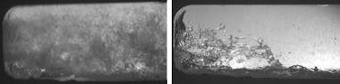
The flow pattern that provides the best distribution is the mist fluid regime. Mist regime cannot be achieved in BPHEs. The second best distribution is achieved in the froth or bubble flow regime, which can be obtained in BPHEs according to above.
By increasing the dimension of the connection, we move vertically upwards in the graph. By increasing the X inlet value, we move horizontally to the left in the graph, (see Fig .9).
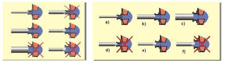
¶ Inlet and outlet connection recommendations for evaporators
In addition to velocity and flow pattern the connection and pipes should be selected to fit port size. This is important to avoid extra pressure drop (if the diameter changes several times) and to avoid regions where liquid refrigerant can be stagnant.
¶ Messages
There are three types of messages:
- Error messages: critical message that indicate an improper selection of a connection
- Warning messages: important message that indicate information the user should be aware of
- Information: mentions interesting information about the calculation